Introduction

Important
Welcome to the Computer Science Open Evening!
This website is a portion of the REAL notes that I have been creating, from Year 12 to now. Feel free to explore the website,
Welcome to my unofficial textbook for OCR A Level Computer Science (h446).
This book is actually just my notes organised in a way that is somewhat semblent of a textbook.
Please fact check a solid portion of the content against the spec, its very likely that information here is NOT what the exam board wants.
If you are taking AS-Level rather than A-Level, refer to the specification for what’s necessary and what isn’t.
A live dev version can be seen on dev.kyuun.tech, which is only live whenever I have my editor open and I am actively writing parts of the book. It may contain changes that are not present on the live/stable version at book.kyuun.tech!
Important
Please note that this book is under HEAVY construction since I’m still going through the spec myself If you are reading this on Open Evening, welcome! A large portion of the book will also need to be refactored and restructured. If there is a mistake, or you want to contribute a page, please send a pull request on Github!
The last update was:

See changelog here
Changelog:

28/3/26 - v0.1.3
- Finished 1.1
16/3/26 - v0.1.2
v0.1.1 and v0.1.0:
- Created the damn thing i forgor what i did before this
Acknowledgements
Massive thanks to the following people:
- No Boilerplate for the excellent resources on Rust, memory management, and everything else in that area
- jhult for their fork of mdbook fixing my sidebar issue
- CXS, for being a brilliant teacher despite the hiring issues at the start of the year
- All the maintainers of rust-lang/mdBook for being chads
- And you, the reader for making this (not really) worth it
Sources for information include:
- Wikipedia
- Issac Computer Science
- My own SLRs
- Physics and Maths Tutor
Please refer to the above for any additional information or clarification!
Systems architecture

Note
🚧 This page is currently being worked on. Please check back soon.
1.1.1 Structure and function of the processor

The CPU (central processing unit) is the primary processor within a computer that is responsible for fetching, decoding, and executing instructions in order to process data and execute programs.
The CPU is split into a few different subcomponents.
Control Unit
The control unit (CU) is responsible for managing and directing the whole processor. The CU will decode the instructions using a binary decoder and perform any actions necessary to coordinate other components.
The CU is responsible for:
- Sending control signals to the memory controller for memory read/write operatins
- Decoding instructions
- Managing the ALU and its operations
Tip
If anything requires sending a signal, it’s often the CU responsible
Clock
The clock is an internal timer used by the CPU to coordinate and synchronise the processor’s operations.
The clock involves a continuous oscillaton between 0 (low) and 1 (high) states.
A clock period is the same as a wave period, which is the time between two high states or two low states.
Note
One CPU operation or instruction can take several clocks. For example, memory read/writes are infamous for being slow.
There are also additional CPU instruction sets, such as AVX-512 that involve significantly more complex instructions that require many more clock cycles to complete.
ALU
The ALU is responsible for any arithmetic or logical operations that need to be carried out.
The result from the ALU is automatically moved into the ACC.
The ALU generally performs the following tasks:
- Addition
- Subtraction
- Multiplication
- Division
- Boolean evaluation (AND, OR, XOR, NOT, etc)
Registers
Registers are small sections of the CPU that store data that is currently in use by the CPU. They are often only a few bytes wide (generally 16-128 bits wide), where the current standard is for CPUs to have their general registers at 64 bits.
Registers are the fastest data storage since they are embedded directly onto the CPU’s silicon.
There are both general use registers and dedicated/special use registers. The special use registers are named and have specific functionality within the CPU. General use registers can be used by the programmer (or compiler) to allocate data as desired. Often times, the general purpose registers are used as additional accumulators.
Tip
Many of these registers are self explanatory, so fall back on that in an exam where necessary!
Program counter
The Program Counter (PC) is the register that stores the address of the next instruction to fetch from memory and execute.
For example, if the CPU was about to execute a program and the first instruction of that program was at index 599, that is what would be stored in the Program counter.
Memory Address Register
The Memory Address Register (MAR) is a register that stores an address in memory where data is about to be read from or written to.
For example, if the CPU needed to read from a specific memory address (0x696969), this address would be stored in the MAR and then passed through the address bus.
This register will store the address that is going to be used for the next memory operation, whether it’s a read or write.
Current Instruction Register
The current instruction register is a register that stores the instruction that is currently being executed by the CPU. Pipelined CPUs will often have several CIRs to contain the instructions that are still being processed through the pipeline.
CIRs are necessary because of potential memory read/writes requiring the MAR and MDR to be populated with other things, so the instruction being executed is moved into the CIR to not be overwritten.
Memory data register
The memory data register (MDR) is the register that stores data that is about to be written to memory or data that has just been read from memory.
Tip
It can help to internally refer to this as the Memory Buffer Register (MBR), since that is a better descriptor of what this register actually does. OCR’s mark schemes have stated in the past
Allow Memory Buffer Register for MDR.
This register is often populated with results from the Accumulator, or with data that has been read from the system memory and passed through the Data bus.
This register is necessary since memory read and write operations are incredibly slow relative to the rest of the CPU due to the difference in clock speeds, so storing data here during a memory read/write reduces the chance that the CPU will stall from waiting for the memory controller.
Placing data into the MBR ensures that the memory controller (connected to the data bus) can read/write at its own pace, without forcing the whole CPU to wait for it.
Accumulator
The Accumulator (ACC) is the register that stores the result from the ALU. The two are directly connected, where the output of the ALU is automatically moved into the ACC.
Status register
Caution
Not clear whether this is in the spec.
The status register (SR) is a register that contains different flags regarding the state of the CPU. Generally this will contain information regarding the last operation from the ALU.
Each bit of the status regiter correlates to a different flag. So the first bit of the SR could correlate to whether an arithmetic operation contained a carry, while the second bit could be whether to disable or enable CPU interrupts.
These are often the same size as the word size of the CPU (64, 32, 16 bit, etc.)
Interrupt Register
Important
This register is important within 1.2.1: Systems Software. Refer to that chapter for more information
The Interrupt Register (IR) is a special use register similar to the SR where each bit correlates to a different interrupt.
Different interrupts will have a different bit assigned, which is also used to identify where the interrupt originated from.
At the end of each FDE cycle, the CPU will check the interrupt register for any unmasked interrupts or any interrupts that are higher priority than what is currently being executed and then set the PC’s contents to the address of the associated ISR if necessary.
Buses
The CPU contains different buses which are responsible for communication and the transfer of data between components.
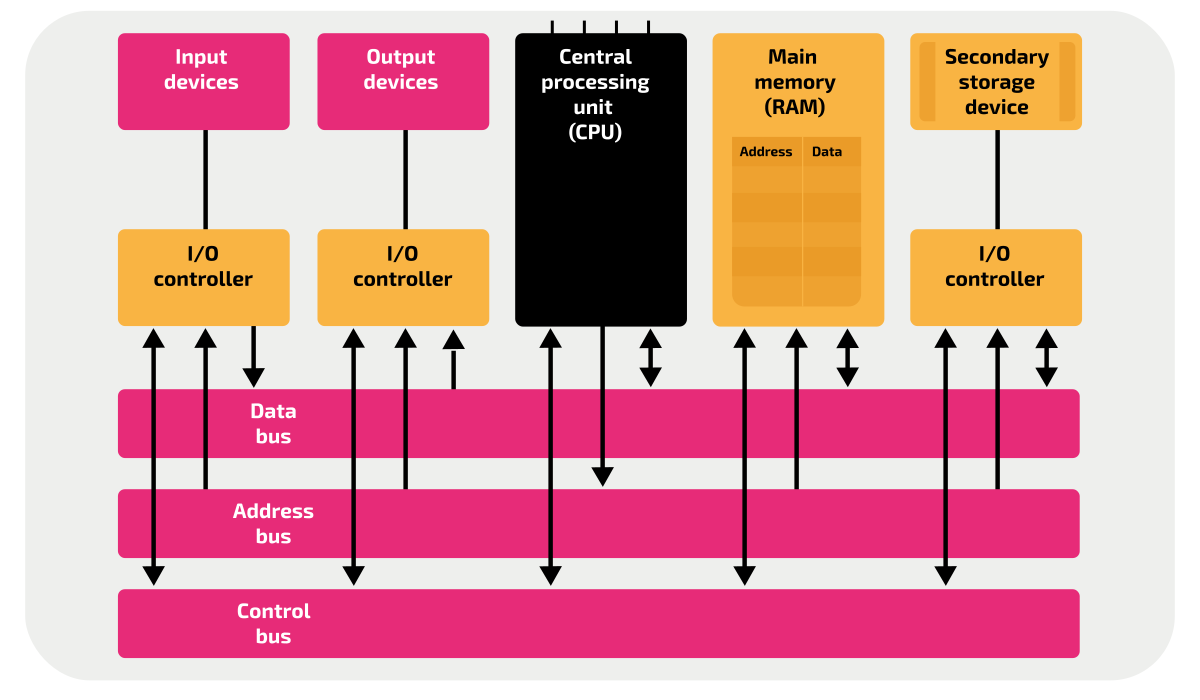
System buses are composed of parallel connections that connect two or more components within the CPU.
External buses are buses that connect the CPU to external components such as peripherals.
The width of a bus determines how many bits can be transferred in one operation, often in multiples of 8 bits.
Address bus
The address bus is a bus that connects the CPU’s MAR to the main memory and I/O controllers. It is unidirectional outwards from the MAR.
The width of the address bus determines how many memory addresses can be accessed. An address bus with a width of n bits, then there can be \( 2^n \) possible addresses. This is also the limiting factor in the total memory capacity of a system.
Data bus
The data bus is a bidirectional bus that connects pretty much everything to the CPU. It can contain data and addresses.
The data bus can allow data from input devices to be passed into the CPU, and also data to be written to output devices from the CPU.
Control bus
The control bus is a unidirectional bus that transmits control signals from the CPU’s control unit to other components inside and outside of the CPU.
The control bus is used for tasks like:
- Memory read
- Memory write
- Bus requests/grants
- Interrupts
- Clock signalling
FDE Cycle
When the processor needs to carry out an instruction, it will perform the FDE Cycle.
The FDE cycle is a set of 3 stages that the CPU repeats in order to execute an instruction.
The FDE cycle assumes that the instructions are already present in RAM as machine code.
Fetch
The FDE cycle begins with fetching the next instruction from RAM.
As stated before the PC contains the address of the nexxt instruction to be executed, so the address in the PC is copied into the MAR before being incremented to the next address for the next cycle.
Important
In the case of a branch, interrupt, or any other circumstance where the next instruction is not at n+1, the PC will be set accordingly
The MAR now contains the address of the next instruction. The CU can now issue a request to the MAR to pass the address down the address bus, and then issue a memory read signal to tell the memory controller to copy the value stored at that address into the MBR, moving it through the data bus.
Now that the MBR contains the next instruction, copied from the main memory, the contents of the MBR are copied into the CIR to be used in future stages.
This is because operations from the instruction being executed may need to utilise the MBR.
Decode
The decode stage involves converting the instructions fetched into the opcode and operand needed to actually determine and execute the new instruction.
The opcode determines what operation to perform, while the operand are the ‘arguments’ to the operation, such as registers, addresses, immediate values, etc.
Note
I think that’s it for this section, I don’t actually know and the spec is vague anyways
Execute
Now that the instruction has been decoded, it can now be executed.
At this point, the CPU’s execution can vary since it will depend on what instruction is currently being executed. The following are some common situations.
| Arithmetic | The numbers are fetched from memory and stored in the general purpose regsters, where the ALU performs the operation on them, storing the result into the ACC. |
| Logic | Two booleans are evaluated by the ALU, often stored in the GPRs or the MBR, or wherever |
| Memory write | The value being written to memory is copied into the MBR, and the address to write to is copied into the MAR. The CU issues a memory write request, where the address is copied through the address bus to the memory controller. The memory controller receives the data to write through the bidirectional data bus, where it can then write the data to the memory address specified. |
Pipelining
Pipelining in the CPU is where the CPU will separate instructions into a variety of different stages in order to parallelise the execution of the instruction.
This in turn can increase efficiency and processing speed. In modern computers, this is possible because of different parts of the control unit being used to perform different things such as the fetching being done separately to the execution.
In cases like the FDE Cycle, the stages are quite distinct, isolated, and repetitive so they can be pipelined. By utilising additional registers to store the intermediate results of the different stages, the different stages can occur at the same time (for sequential instructions).
The following diagram (from wikipedia) is the best descriptor of this.

Caution
Some of the following sections are copied directly from my SLRs. Rewriting them will occur later if ever
CPU Model Architecture
The CPU is often abstracted into two models, the Von Neumann Architecture and the Harvard Architecture. Both of these concepts are useful in modern processors, however a mix of the two is generally used in modern systems.
Von Neumann
The Von Neumann model is the first and simpler model, where the instructions and data are stored in the same space in memory. The memory and data bus is also shared in the VNA, which can potentially lead to bottleneck issues when transferring larger and larger amounts of data.
The Von Neumann bottleneck is a consequence of only having one bus between memory and the CPU. The bus can only read data or memory one at a time, limiting the CPU throughput significantly. VNA also has the consequence of potential for overwriting code by accident, since data and instructions are stored in the same location.
Harvard
The Harvard architecture was designed to improve upon the Von Neumann architecture, where instead of having a unified bus and cache for data and instructions, it would separate to two to allow for concurrent read and writes.
This in turn can increase the overall performance, as the CPU can do 2 slow operations at the same time, instead of doing them in sequence. The division of the instruction and data memory also means that they can be resized accordingly, improving optimization and making it more flexible for the developer if they wanted to have different properties for each type of memory. (RO or RW, etc.)
The Harvard architecture also has the benefits of being able to utilise Out-Of-Order Execution (running independent instructions while waiting for IO bound instructions to complete, preventing pipeline stalling), superscalar execution (multiple instructions in one clock cycle), and other execution optimisations.
-
Credit to Isaac Computer Science, under OGLv3. ↩
1.1.2 Types of processor

We have many different types of processor, all designed to complete different tasks. Some processors are designed to accelerate specific tasks, while others are designed to be general purpose.
CPUs can be separated into two families, being CISC and RISC.
Processor architectures
Rising from different philosophies, modern processors fall under two groups, being RISC and CISC. They both have different properties, pros, and cons that may make one architecture more suitable than the other.
RISC
RISC (Reduced Instruction Set Computer) is one of the two main CPU architecture in use. It is present in most mobile devices, embedded computers, microcontrollers, and is growing in use in laptops and servers particularly by Apple with their M-series and Qualcomm with their Snapdragon X lineup.
RISC processors maintain the philosophy of one operation per one instruction within one clock cycle.
This results in RISC processors having much fewer and less complicated instructions compared to CISC since they perform less and theres fewer operations that need to be given a dedicated instruction.
Something simple such as adddition could take many instructions such as loading the values from memory and then calling the add instruction.
Additional traits of RISC:
- Easier to pipeline since each instruction is predictable and simple
- RISC programs require more ram to store the additional instructions
- RISC processors are generally more power and heat efficient
- Fewer abstractions
CISC
CISC (Complex Instruction Set Compiter) is the CPU architecture most commonly used in desktops and laptops.
Note
For additional reading on CISC instructions, see this video on strange x86 CPU instructions
CISC processors are significantly more complex (hence the name) compared to RISC processors, as these processors are capable of having single instructions that can perform multiple tasks.
Generally, these instructions wrap around the simpler instructions.
For example, the instruction DPPS ( Dot Product of Packed Single Precision Floating-Point Values) from the AVX SSE4.1 instruction set does significantly more than just one operation.
CISC processors will have more instructions than RISC, since there’s more clock cycles that can be allocated to a single instruction.
Additional traits of CISC:
- Simplifies compilation because the instructions can more closely resemble higher level statements
- Could also make the optimization stage more difficult
- Less heat/power efficient
- Physically larger
- Lower memory usage#
Parallel processing
Parallel processing is where multiple tasks are completed separately from each other, resulting in all of the tasks being completed in a shorter time than if they were to be executed sequentially.
Systems with more cores are capable of executing more tasks in parallel.
For systems without multiple cores, a single core can make use of threading, which is a form of concurrency on a single core.
Caution
Concurrency and parallelisation ARE DIFFERENT.
See this video (2:04-3:07) for the explanation, though I highly recommend watching the whole video.
Feel free to ignore the Rust specific parts. From what I know this is on the specification.
The negatives of parallel processing
Parallel processing may not guarantee a speed increase. Often, it can cause bugs and rarely cause slowdowns.
When performing parallel processing, the task needs to be allocated to the different cores/processors, which induces a small overhead.
In the cases of small tasks being parallelised, the overhead of allocating many different tasks could overshadow the speed benefit of parallelising the task in the first place.
Parallel processing is also significantly harder to program and utilise.
The Rust Programming Language Book phrases this very well:
Splitting the computation in your program into multiple threads to run multiple tasks at the same time can improve performance, but it also adds complexity. Because threads can run simultaneously, there’s no inherent guarantee about the order in which parts of your code on different threads will run. This can lead to problems, such as:
- Race conditions, in which threads are accessing data or resources in an inconsistent order
- Deadlocks, in which two threads are waiting for each other, preventing both threads from continuing
- Bugs that only happen in certain situations and are hard to reproduce and fix reliably
These possible circumstances make development and testing with parallelism very difficult in comparison to single threaded programming. It’s up to the programmer to determine whether it is worth it or not to implement parallelism/concurrency.
Coprocessors and Accelerators
Along with our primary processor (generally the CPU), there can also be additional processors that tasks can be delegated to.
Co-processors are specialised processors that are capable of doing specific tasks much faster than the CPU can. Things like floating point arithmetic, cryptography, matrix multiplication, and other easily parallelised tasks are frequently offloaded to such coprocessors.
Hardware acceleration will often use coprocessors such as a GPU or NPU/TPU, which will offload computationally intensive tasks onto the additional device. This can improve render times and performance overall as these devices are Mathematically intensive tasks like rendering, ML workloads, etc, will almost always be offloaded to the GPU, as it is able to perform orders of magnitude faster than the CPU in these tasks.
Here are some common coprocessors:
Note
You don’t need to know any of these except for the GPU.
| Acronym | Full name | Task |
|---|---|---|
| GPU | Graphics Processing Unit | Rendering graphics, Parallelised arithmetic |
| NPU | Neural Processing Unit | AI and machine learning |
| TPU | Tensor Processing Unit | Variant of an NPU by Google for neural networks |
| QPU | Quantum Processing Unit | Quantum computing |
GPUs
The GPU (Graphics processing unit) is a specialised processor originally designed to accelerate the computation of graphics and 3D space.
GPUs in comparison to CPUs will instead pack the die with thousands of cores to maximise the capabilities of the parallel processing.
Since the only thing the GPU will be doing is completing tasks sent from the CPU, it does not need nearly as much silicon space for administrative parts.
| GPU | CPU |
|---|---|
| More cores | Less cores |
| Simpler cores | complicated cores |
| Specialised for parallel processing | Specialised for sequential processing |
| Computes more specialised tasks | Computes more general tasks |
1.1.3 Input, output and storage

Input and output devices are how we interact with a computer. Without them, a computer is just a box that creates heat.
Note
This chapter is really short since a large portion of this is GCSE content.
Different devices can be used for different purposes
Input devices
Input devices are devices that provide data or information to a computer. This could be in the form of signals, data, or any other arbitary message.
Common devices include:
- Keyboards
- Microphones
- Cameras
Output devices
Output devices are devices that respond to data provided by the computer to create a perceptible response.
Common devices include:
- Headphones
- Speakers
- Displays
- Printers
Storage devices
Throughout the years, we have developed different ways of storing data on physical mediums. Each of these different storage devices have different advantages and disadvantages.
CDs and Optical media
CDs are able to store data by burning small indents (pits) into a polycarbonate (plastic) disc using a laser.
When reading from a CD, the laser shines light at the spinning disc. As it rotates, the light will encounter either a pit or a land. Each pit represents a 0, since light is scattered instead of being reflected. Where there is no pit, a land is present, which represents a 1 due to the light being able to reflect back.
CDs are also separated into many sub-categories.
Format-wise, the 3 types are CDs, DVDs, and BluRays.
DVDs were invented as a higher capacity version of CDs, where it allowed data to be stored on two layers of the disc. This increased capacity significantly, where the size of DVDs ranges from a max of 4.7GB on single layer, or 8.5GB on dual layer DVDs.
BluRays currently offer the highest capacity of the optical storage mediums, thanks to their blue laser having a shorter wavelength. There are several formats of BluRay, ranging up to 4 layered discs, with a maximum capacity of 128GB. The standard single layer BluRay has approximately 25GB of storage per layer.
Optical storage is also separated by their readability. CDs and DVDs come in ROM, -R, and -RW variants.
ROM variants can only be written to once, often in factories. This variant is generally used for media distribution, such as music.
-R variants stand for “recordable”, and are distributed without any data, and the user can write data once but never again. This is generally used for archival purposes, such as old photos, videos, etc.
-RW variants stand for “Read write”. These discs can be written to multiple times, and are the most versatile of the three.
HDDs and Magnetic storage
Magnetic storage devices are some of the most common storage devices. These store data by manipulating the polarity of a magnetic platter.
Magnetic storage devices include HDDs, floppies, and tapes.
HDDs work by spinning a cobalt alloy disc (the platter) at high speeds, where a read head containing another magnet can read and alter the magnetisation of small parts of the platter. The rotation speed is a primary factor in the read speed of the disc, since the read head can get to specific parts of the platter faster.
The performance of a HDD can vary significantly. Since HDDs rely on physical movement, to access different data locations, data can become fragmented across a drive, where different parts of a file or folder are physically separated on the platter. Fragmentation can hinder read-write speeds, since the drive will need to wait for the rotation to finish to get to those sections.
Fragmentation is caused where there is not enough contiguous space to store the whole file, so the HDD will store the file in the next available location.
HDDs also are quite easy to recover data from, since the first thing to fail in the HDD is the rotational mechanisms or the read head. The platter can often be transplanted to recover the data.
In addition, HDDs are very good in their cost efficiency. High capacity HDDs are often cheaper than high capacity SSDs (especially during the current shortage as of early 2026).
HDDs however are not robust, and vibrations or movement can hinder or even stop a HDD from working correctly during the movement.
Their speeds being limited to physical movements are also a limiting factor. Server grade and enterprise HDDs only go up to a maximum rotation of 15,000 RPM, which is significantly slower than the read speeds of SSDs.
SSDs
SSDs are the current modern storage technology, making use of flash memory to store data.
SSDs contain no moving parts, making them less prone to failure and damage, and also significantly faster than HDDs since they don’t rely on needing to spin to the data physically.
SSDs are also more robust for the same reason, meaning that they are are more suitable for devices that constantly move, such as laptops.
SSDs however have shorter lifespans. This is mainly due to write limits and bit-rot. Each memory cell has a limited number of write limits, as writing data physically degrades the flash memory cells. Bit rot is the slow loss of charge of the stored data where bits can flip if left unpowered for long periods.
SSDs are currently the fastest developing technology as well. The current maximum SSD capacity is ~245TB, held by Kioxia for data centre usage. SSDs are also faster than HDDs in almost all cases. The extent of this depends on the type of SSD, either SATA (the most common connector, shared by HDDs and SSDs), or NVMEs which is a protocol that uses PCIe to increase transfer speeds.
NVMEs have a max read speed of ~14,000MB/s (PCIe 5.0) and SATA has a max read speed of 600 MB/s.
SSDs unfortunately are much more expensive in general (especially now during the current shortage from companies moving to High Bandwidth Memory production for AI) than other storage technologies.
Note
Please check out Isaac Computer Science for more information about how exactly data is stored in these storage mediums. It doesn’t appear to be in the spec, so I have omitted a lot of that information here.
Virtual Storage
Virtual storage is a software based solution to having multiple drives. Essentially, it abstracts away the physical drives, presenting every drive as one massive storage device. Virtual storage is generally used for NASes, cloud storage, or any other remote storage that is not physically on your device.
Virtual storage is generally useful for the convenience of not managing many drives at once, however it does also provide extra benefits.
Utilising virtual storage allows you to separate data across drives, and also provide redundancy. For example, if you have 4 drives, you can use 3 of them to store data, and the 4th drive to store a small amount of duplicated data from the other 3 drives. This way, if one of the drives fails, you can still recover some of your data from the backup drive.
Note
For more information, check out RAID which is a common implementation of virtual storage with parity and distributing data across multiple drives through striping or mirroring.
Suitability of different storage devices.
Each of these storage devices are suitable for different situations. In the exam, you may be asked to provide a storage device and explain why it’s good for that specific scenario.
Generally, it can be shortened to:
| Needs fast read/write | SSD |
| Needs high capacity | HDD/SSD |
| Needs cost effective storage | CD, HDD |
| Needs to move data safely | CD, SSD, Cloud |
| Needs portability | SSD, Cloud |
| Needs small form factor | USB sticks, NVME SSD |
Software and software development

Note
🚧 This page is currently being worked on. Please check back soon.
1.2.1 Systems Software

Operating Systems
An operating system manages hardware and software resources, as well as providing an interface between user and hardware.
Resource Management
The first of seven categories, the OS is responsible for resource management. They allocate resources (RAM, CPU, and Storage) to specific tasks and try to maximise performance and power-efficiency. For example, the scheduler in an OS is responsible for prioritising what runs next on a CPU, so if you, for example, open a game, it will prioritise allocating resources to that, rather than OneDrive syncing in the background (more on these later).
File Management
The OS is also responsible for file management - that is, working with the file system that the drive is formatted with in order to store, retrieve, and manipulate data. OSes will provide some sort of user interface, usually a GUI, to allow the user to interface with the file system and gives files properties e.g. file names, directory the file is stored in, dates modified, EXIF data, etc.
Interrupt Handling
Interrupts are events that require the immediate attention of the CPU, such as mouse movements. These must be processed quickly in order for the system to feel responsive and respond to time-sensitive actions e.g. cancelling file deletion (more on these later).
Security
Operating systems usually provide some sort of security suite such as a firewall (e.g. nftables), virus scanning (e.g. Windows Defender), and file encryption (e.g. BitLocker). Different accounts on the system can be given various permissions, such as file permissions, being allowed to install software globally, and editing the firewall settings, etc.
Providing a Platform for Software
Software from third-parties will need to access system resources, and this is the responsibility of the operating system. This is done via system calls (syscalls), where a program will ask the opearting system to give it access to resources to allow it to carry out a task e.g. write data to a file, or render triangles on a GPU.
Providing UIs
Users need User Interfaces (obviously) in order to interact with a computer. An operating system at the very least will provide a CLI (command-line interface), but usually a GUI (graphical user interface) too. On mobile OSes such as iOS the CLI is usually hidden and only used for debugging, as mobile OSes need to optimise for ease-of-use through touch-friendly GUIs.
Note
Not all OSes provide GUIs, such as server OSes where a GUI would just consume unnecessary resources and would never be ued.
Utility Software
Utility software allows for the maintenance of the hardware and software systems running a computer. OSes will usually include at least a very basic set of utility software such as disk formatting, file compression, and package management.
Interrupts
A device or a piece of software can generate an interrupt and send this to the processor to trigger an ISR (interrupt service routine). They are used for handling real-time events such as mouse movements, device communication such as incoming network connections, and multitasking. They are concise and have a specific purpose.
| Type | What it does |
|---|---|
| Hardware Interrupts | Asynchronous interrupts generated by external devices, and will cause an ISR to run that will, for example, process a keyboard input in a game. |
| Software Interrupts | Synchronous interrupts triggered by software or the OS itself, often generated when errors occur e.g. a network error, but also when I/O operations are needed such as when opening a file. |
| Trap Interrupts | A type of software interrupt triggered by a user program’s instruction, such as a system call or an exception like division by zero, which forces the CPU to switch to kernel (low-level OS) mode and execute a handler before returning to the user process. |
Note
A kernel is often referred to as the ‘core’ of an OS, which handles the interface between hardware and software and contains software such as basic device drivers and the code to power on a system once the BIOS/UEFI has handed it control.
If the interrupt is of a lower/equal priority to the current process then the current process continues. Otherwise:
- The contents of the registers are copied to a stack (special area of memory).
- The interrupt flag is set.
- The program counter is changed to point to the ISR. If a higher-priority interrupt comes in during handling, the lower-priority interrupt is added to the stack and the higher-priority one is dealt with first. Interrupts can also be nested, where an ISR could trigger another interrupt, and the CPU deals with these.
- After the interrupt completes, the previous register values are restored back from the stack and the interrupt flag is reset.
Important
Interrupts are not always run - masked interrupts are hardware interrupts that can be ignored or disabled by the system using interrupt-masking techniques, selectively ignoring non-critical interrupts. They help in managing system resources and are used routinely during normal system operation.
1.2.2 Applications generation

Stages of compilation
Compilation is split into several stages:
Lexical analysis
The source code is parsed, removing unnecessary whitespace and comments.
From the remaining code, is then tokenized, producing a token stream, where information about keywords and identifiers are collected into a symbol table.
Syntax analysis
The token stream is first analysed and checked against the syntax of the language, ensuring that there are no syntax errors.
In the case of syntax errors, the errors are thrown with diagnostic information.
After the token stream is confirmed as syntax error free, the stream of tokens is parsed to produce an AST (Abstract Syntax Tree).
The AST represents the structure of the program in a tree like structure. This process will result in additional information being added to the symbol table, such as datatypes, scoping rules, etc.
Semantic analysis
The AST is checked for semantic errors. These are any non syntactic errors or logic errors, such as:
- Incorrect types
- Multiple variable declarations
- Undeclared variables
Code generation
The AST is used to produce object code that represents the program functionality.
At this point, the object code is not executable, because it has not undergone linking.
Optimization
The generated object code is optimized. This can result in:
- Improved runtime performance
- Reduced memory usage
by: - Removing redundant/inaccessible code
- Optimizing loops
- Switching functions that evaluate to constant values for a constant value.
Linking
When programs are compiled, they often depend on third party code in libraries that need to be discoverable by the program before it can run.
There are two types of linking, static and dynamic
Static Linking
Static linking is where the third party libraries are embedded inside of the executable.
This is done by the compiler, where the object code from the libraries is packaged alongside the executable during link-time, producing a singular executable that contains its own dependencies.
| Pros | Cons |
|---|---|
| The executable is ‘portable’ and can be copied to other systems on its own | Larger binary size |
| The executable is standalone and requires no other third party libraries | Longer overall compile times |
| Third party libraries updating doesn’t affect the executable, since it uses its own versions | Could potentially be redundant if the same libraries and versions of those libraries are present on the system |
Dynamic Linking
Dynamic linking is the opposite, where the application does not package its own libraries, and relies on them being present in the runtime environment.
This is done by providing the compiled executable with the library’s symbol names, metadata, and references, without copying any of the code from the library. This means that the program is able to call code from the library, if the code was present.
To ensure that the code is present at runtime, the operating system can use a dynamic linker to load the third party shared libraries into memory, then bind the symbols to the correct address in memory where the library’s code is now present.
Dynamic linking can also make use of lazy loading, where the functions of the library are only loaded into memory when requested by the program. This can reduce the initial load time and memory usage, however the first function call will be slower, since you essentially just moved the loading from the starting of the program to now.
| Pros | Cons |
|---|---|
| Multiple applications depending on the same version of the same library can use the same libary file | The library version present at runtime needs to be compatible with the version that the program was compiled with |
| Saves overall disk space if multiple applications use the same library. | Dynamic linking can result in slower runtime performance |
| Memory usage can be shared if multiple running applications need to use the same librrary | |
| Easier to update libraries together |
1.2.3 Software development

SDLCs
When developing software, teams will often utilise different software development lifecycles (SDLCs) in order to organise and schedule development.
Stages of an SDLC
SDLCs are generally split into a few common stages to describe the different stages of development during a project’s lifecycle.
Analysis
In this stage, the stakeholders will first provide the requirements for the finished product. These requirements will be used to
- Define the problem
- Estimate the feasibility of the project
- Deciding on the scope of the project
- Determining profitability
The point of this stage is to understand the problem provided by the stakeholders, decide whether the project is worth or possible undertaking, and what they want the finished product to be able to do.
This is essentially the same as the analysis section of the programming project.
Design
Design is where the requirements provided in the analysis stage are converted to a project plan.
This is where technical details such as choice of language, framework, hardware, etc will be made.
Most aspects of the program will be identified and scaffolded in this stage, such as:
- Inputs
- Outputs
- UI design
- Security
- Performance
Development
This is where a large portion of the project’s lifecycle will be.
Development is where the plan created in design will be converted into a collection of modules, where teams can then be allocated to work on coding the program.
Modules are ideally self contained, as this improves the ability for a team to work in parallel.
Testing
Testing is grouped into different categories to fit different stages of development. These strategies will be ideal for different circumstances, and will have different objectives or focuses.
White box testing
White box testing is the in-house testing of the code’s structure and algorithms. White box testing focuses on the code itself, and therefore requires knowledge of how the code is written. White box testing is used across the development cycle, and is consistently used to monitor for regressions.
White box testing often involves:
- Unit tests
- Valid, invalid, boundary and erroneous data
White box testing is often automated using Continuous Integration (CI) tools, or utilities that are part of the language/framework’s ecosystem, such as cargo test in the Rust ecosystem.
Black box testing
The goal of black box testing is to check the functionality of the program, ignoring anything unrelated to such, including the code quality or structure.
Black box testing is performed by the end users, where their feedback will be used to refine the functionality.
Alpha testing
Alpha testing is any testing performed by the in house developers, or other employees of the development company/department during the development stage. This will involve the early release of an in-development build of the program, where features may be missing or non functional.
Alpha testing will focus on pinpointing and fixing early bugs that may critically affect the program, and to give an idea of the current state of development.
Beta testing
Beta testing is carried out similarly to alpha testing except instead with the end user using the build, where they will be allowed to use the program as they expect. The beta build will be often made after the main development has completed and functionality is present. The end user will then provide feedback to the developers on any remaining issues regarding the program.
Beta builds are often very close to the final release of the program, where the only thing stopping the final release is quality control.
Warning
Regression and acceptance testing are not in the specification. However it’s probably good to know
Regression Testing
Acceptance Testing
Implementation
After a build is passing all tests and has been approved by the client, the program can then be installed onto production servers or systems. Implementation also often involves the additions of application tweaks such as DRM and digital signatures. It can also involve setting up distribution, such as pushing updates or creating download servers/CDNs
Evaluation
Maintenance
System development methodologies
The above stages can be grouped together in different ways to create System development methodologies, which determine how teams will approach the development of a project.
Waterfall
Waterfall is a linear SDLC where each stage is completed sequentially, cycling round each time. The structure is highly rigid, where if the team needs to go back to a previous stage, the stages from then and the most recent stage must als obe repeated. In addition, the users generally only give any feedback to the development team near the start or end of a waterfall cycle, therefore making changes is tedious and difficult with this paradigm.
Advantages:
- Clear milestones
- Easy to produce good documentation
- Simple management
- Very predictable
- Well understood and well known
Disadvantages:
- Inflexible to requirement changes
- Mistakes need to be caught during the stage they appear, otherwise backtracking stages is expensive
This is probably the simplest SDLC, but is also being phased out for the agile methodologies .
Spiral
The Spiral model is a similarly iterative SDLC that takes the ideas of Waterfall, but injects additional risk assessments after the analysis stage. The spiral model is generally split into four stages in the following order
| Stage | Purpose |
|---|---|
| Analysis | Identifying requirements and feasibility |
| Risk assessment | The risks are identified and mitigated where possible |
| Development | The project is developed and tested |
| Evaluation | The project is evaluated for how successful it was, and the next spiral continues as the next iteration |
The spiral model is used for projects that are high risk and high cost, where the additional risk assessments are necessary. Every spiral’s evaluation stage will feed into the next spiral’s analysis to inform the next iteration.
Advantages:
- Extensive risk management
- Evaluation feeds into the next iteration
- Simple
Disadvantages:
- Costly
- Time consuming
Rapid Application Development (RAD)
When the inital requirements are unclear and the project scope is relatively small, RAD can be used.
RAD is an iterative methodology that involves the development of many early prototypes that are then presented to the client.
The development team will take the feedback from the client to produce the next prototype.
Eventually, after enough early prototypes, the prototype will match the requirements of the client, where it can then be presented as the finals solution.
Advantages:
- Fast delivery of functional prototypes
- strong user involvement
- flexible to requirement changes.
Disadvantages:
- Less suitable for very large systems
- Potential for scope creep
- Depends on availability of end users.
Agile
Agile describes a family of iterative methods that prioritise flexibility during development. Generally, the development team will focus on different aspects of the project at the same time, therefore allowing development to be completed in parallel.
The team will focus on producing a prototype early on which can be presented to the client for feedback. This delivery of prototypes continues throughout the lifecycle as well.
Advantages:
- Frequent prototypes
- Continuous customer feedback
- Versatile
- Common in workplaces
Disadvantages:
- Requires disciplined teams
- Requires constant stakeholder engagement
🔥Extreme Programming🔥
Extreme programming is a subset of the Agile methodology that emphasises engineering practices to improve code quality and responsiveness.
Extreme programming generally involves pair programming, test‑driven development (TDD), continuous integration, simple design and small frequent releases as these are all techniques that focus on specific code quality.
Advantages:
- High code quality
- Rapid response to change
- Strong developer collaboration.
Disadvantages:
- Requires more teamwork
- Requires 2 developers per section/session
- Clients may not be available
1.2.4. Types of Programming Language

Programming languages follow different paradigms, depending on the philosophy of the community and decisions by their creators.
A programming paradigm is the style or model in which a programming language uses.
Different languages utilise different paradigms, or can even support multiple, becoming the programmer’s choice as to which to use. Some paradigms will be more useful in solving a specific problem than another, therefore it should be decided which to
Warning
Function and procedure are used mostly interchangeably by me within this chapter. Functions return a value, procedures do not. This is an important difference that you should take note of.
Procedural languages
TLDR:
- Programmer specifies steps needed to complete the program
- Statements are grouped together in procedures and functions
- Variables can have varying scope (local/global)
- Logic is expressed in chains of imperative procedure/functioncal calls
Procedural is the easiest and simplest paradigm, involving a chain of instructions that are executed sequentially. The execution of the program goes from top to bottom, where most functionality is contained within defined, imperative functions.
Procedural languages are the stereotypical programming languages, making use of the typical concepts of data structures, sequence, selection, iteration, functions, etc.
Variables in procedural languages are defined to have either a local or global scope.
- Local scope is where the variable is obly available within the function
- Global scope is where the variable is accessible throughout the program and across all functions
Object-Oriented languages
TLDR:
- Data is grouped into objects
- Objects contain methods and attributes which belong to their instance
- Instances are self contained
- Objects can be reused and inherited across the codebase
- Logic is expressed as the relationship between objects
Note
For the exam, you will need to be familiar with OOP concepts, and how they work in OCR Reference Language
The concept of OOP is to produce reusable, self contained, or encapsulated, objects that interact with each other to form logic and represent data. OOP is frequently used in the modern day due to the self contained nature of different structures. Thus has the benefit of making debugging easy, while also simplifying the relationships between data.
OOP utilises access modifiers to control who or what is able to access the data stored within an object.
The private keyword means that the method or attribute can only be called/accessed from itself.
The public keyword means that other objects can access/call attributes/methods within the class.
For example, consider the following class:
public class Pet {
    // attributes
    public String name;
    public Float hunger;

    public Pet(String name) { //constructor
        this.name = name + " " + "Ayana";
        this.hunger = 10.0;
    }

    //methods

    public String getName() {
        return this.name;
    }

    public void feed() {
        this.hunger = this.hunger - 1.0F;
    }
    private void eat(String name) {
        this.hunger = this.hunger + 1.0F;
    }
}
This is an example of a class, representing a simple pet. The pet has a name that is set when a new pet is created. The name is a property of the class, or an attribute.
The pet also has a method which manipulates the data of the instance of Pet.
The pet also has a private method that only the pet can access.
This pet is encapsulated, where data is self contained, data that relates to the pet is an attribute of the pet, and the data of the pet can be manipulated by using provided publicly accessible methods.
Encapsulation is defined as packaging behaviour and data within a class, and access to a class's data is controlled through **getter** and **setter** methods.

Getters and setters return or set private attributes.
Other objects can inherit traits and attributes from the parent class.
Consider the following child class:
public class Dog inherits Pet {
    //attributes
    public Boolean tailWagging;

    public Dog() { // constructor
        this.tailWagging = true;
    }

    //methods
    public void toggleTailWag() {
        this.tailWagging = !this.tailWagging;
        this.hunger = this.hunger - 1.0;
    }

}
The above class Doginherits the attributes and methods from Pet, even though they aren’t explicitly declared within Dog.
For example, I didn’t declare float hunger; at the top of Dog, yet it’s still accessible within toggleTailWag().
Taking this into account, you can also call the .feed() methods on the Dog class, as it is also inherited from Pet.
Caution
Private methods are not inherited, so you cannot call
.eat()from any subclasses.
However, what if you wanted to inherit from another class, but you needed to modify a specific method’s behaviour?
This can be achieved using polymorphism.
Consider the new mechanical dog that doesn’t need to eat.
public class RoboDog extends Pet {
    // attributes
    private Boolean tailWagging;

    //constructor
    public RoboDog() {
        this.tailWagging = true;
    }

    //methods
    // polymorphism example, changing the behaviour of feed() which we inherited from the parent class
    @Override
    public void feed() {
        throw new UnsupportedOperationException("It's a robot, it isn't hungy!");
    }


    public void toggleTailWag() {
        this.tailWagging = !this.tailWagging;
        this.hunger = this.hunger - 1.0;
    }

}
Since robot dogs cannot eat anything, but are still pets, we need to alter the inherited feed method to throw an error when we try to feed the robot dog.
In Java, this is notated with the @Override decorator (don’t worry about this), telling the compiler that when we call .feed() on an instance of the subclass RoboDog, we need to throw an error. If we didn’t do this, the default .feed() from the parent Dog class would be used, which is not what we want.
This concept of modifying behaviour based on their subclass is referred to as polymorphism.
In short, these child classes (referred to by the exam board as subclasses), encapsulate data and behaviour using attributes and methods, which can then be inherited from the parent class (super class), allowing behaviours to be modified through polymorphism.
Assembly languages
- Low level
- 1-1 conversion to machine code
- Specific to processor architecture
- Uses addresses to reference data
Assembly language is a low level family of programming languages that give you direct control over the machine code being executed by the CPU. You have direct control over what is stored and moved within each register.
Assembly revolves around the concepts of op-codes and operands, which map directly to machine code.
Consider the following LMC assembly:
LDA #50
ADD #1
OUT
In the first line, the instruction is LDA #50, where the op-code is LDA and the operand is #50. The op-code deterines what the CPU should do with the data provided (the operand).
The above program will load 50 into the accumulator and add 1 to it, then outputting it.
Since assembly has almost no abstractions over the raw machine code, things such as data types don’t exist and control flow is limited. Instead, data is read and interpreted as raw bytes, and if statements are limited to jumping to certain addresses based on conditions.
Little Man Computer Instruction Set
Caution
You need to know the instructions in LMC and how to write programs with LMC assembly.
The LMC Instruction Set is a simplified form of Assembly, where you manipulate
Declarative languages
Declarative lanugages are not in the specification, however you will be familiar with them. These are languages that describe what needs to be done, rather than how it should be done, essentially providing what the final result should be. SQL and HTML are considered declarative languages, as they define how the output from the database, or how the website should look.
Functional languages
Functional languages are a type of declarative language. This involves a series of declarations, where functions are continually piped into each other in order to form logic.
See Haskell or Nix for further reading, as these are 2 commmon functional languages.
Addressing Memory
There are several ways of addressing memory with assembly.
| Mode | Interpretation of the operand |
|---|---|
| Immediate | The value is used literally, and is the actual value used in the instruction |
| Direct | The value contains the address of the value which can be read for the value we want. |
| Indirect | The value contains the address of a pointer which is then dereferenced for the value we will use |
| Indexed | The value is added to the index register and then we read from the address inside of the index register |
Exchanging data

Note
🚧 This page is currently being worked on. Please check back soon.
1.3.1 Compression, Encryption and Hashing

Compression is the act of reducing the size of data through different encoding techniques in order to represent the same information with less bits.
Uses of compression
Compression is useful for several reasons:
- Transferring compressed files across a network results in less data transferred overall
- Transferring compressed files across a network results in faster transfers
- Compressing files reduces size usage on the filesystem
Types of compression
While there are many uses of compression, there are also many ways to compress a file. These methods are grouped into 2 categories.
Lossy compression
Lossy compression is where data that is determined to be unnecessary is permanently stripped from the file.
This results in greater compression ratioes (lower file size), but a longer compression time.
This is most common in media files, where a lot of data can be removed, while still maintaining most of the quality of the original media. While some users may be able to perceive the loss of data, the aim is for it to be a minimal loss in quality, or completely negligible.
| Format | why |
|---|---|
| MPEGs | certain pixel data might be omitted if it doesn’t change often |
| JPGs | Things like plain backgrounds can have some pixels stripped of their data if its just a blob of a single colour |
Lossless compression
Lossless compression is where the data is compressed, while ensuring that the original file can be extracted from the compressed file. This involves rearranging the data into some form that is more efficient.
Lossless compression results in significantly less compression ratios than lossy, as it must be able to recover the original file.
This compression type will analyse the sequenceing for the data within the file to find some kind of repetition that can be reproduced in a shorter way. The two main algorithms are:
- Run length encoding
- Dictionary encoding
Run length encoding is where frequently repeated data sequentially is converted into a singular phrase that can be repeated.
Consider the following sequence:
QUUIURWWWWWWIOOOOOOPIUUEW
Some long chains of text can be compressed to reduce the file size.
QUUIUR$6WI$6O$PIUUEW
This takes up less space, while still being able to represent the same data.
You can also recursively apply this.
Consider the following sequence:
UUUUU_UUUUU_UUUUU_UUUUU_A
This can be compressed to:
$4($5(U)_)A
The repeat is repeated, and short sequences that are repeated are also able to be compressed in this manner.
Dictionary encoding is another lossless technique where instead of replacing sequences with repetition, it creates a dictionary and substitutes the repetants (idk) for a reference to the dictionary entry that contains that word or sequence.
Consider the sentence:Rust is my favourite language ever. Rust is very Rusty and I love to utilise Rust's ecosystem. Rust in general is the best programming language ever! Rust is way better than C++!
A dictionary could be created that contains the word Rust.
The above sentence could become:$1 is my favourite language ever. $1 is very $1y and I love to utilise $1's ecosystem. $1 in general is the best programming language ever! $1 is way better than C++!
Dictionary encoding relies on repetition across the file, and sometimes will result in increased file sizes depending on the amount of repetition in the file.
Encryption
Encryption is the process of converting plaintext into ciphertext to prevent data from being interpreted/understood.
Modern encryption makes use of complicated ciphers (algorithms) in order to prevent the ciphertext from being interpreted by third parties.
Cipher strength is the number of possibilities for how a message can be encrypted. This is the metric used to determine how resistant an encryption algorithm is to brute force attacks.
Generally, the strength of a cipher will depend on the length of the key, where more options for keys means that it would be harder to pick the correct the right key.
Cryptanalysis is where a code is being broken without the key being known. Cryptanalysis generally utilises a brute force approach, however it is not completely uncommon for exploits to be found within algorithms.
Symmetric key encryption
Symmetrical key encryption is where both parties share an identical key. When both users have the key, both users are able to encrypt and decrypt data using that same key.
Symmetrical key encryption is harder to keep secure and easier to leak since anyone with the same key will be able to decrypt encrypted messages.
Asymmetric key encryption
Asymmetric encryption is where 2 different keys are generated, known as the public and private key. The public key can be distributed and does not have to be kept secret. The private key must be kept to the individual.
Data encrypted by the public key can only be decrypted by the private key. Since only one key (the private key) can decrypt and it is never shared, it’s significantly more secure than symmetric keys.
The private key can also generate the public key, however the private key is almost completely impossible to be derived from the public key.
Note
Asymmetric key encryption incredibly common, particularly for thing such as digital signatures. This will be extended upon in hashing
Hashing
Hashing is where an algorithm is applied to data to mathematically produce a fixed length string based on a set of given data. It is a one way algorithm, and the original data cannot be recovered from the hash.
Important
Hashing and encryption both produce unreadable strings, however encryption is a reversible process while hashing isn’t
Hashing can be used to ensure data integrity, as if the data changes in any way, no matter how small, the hash will also change.
Good hashing algorithms will:
- Have a sufficient hash length
- Be able to produce a fixed hash length given any sized input
- Low chance of collision
- Be relatively fast/efficient
- Irreversible
Hashing in authentication
Hashing is generally utilised in cases where we want to compare sensitive information to each other. For example, instead of comparing rawtext passwords together, we can instead compare the hashes of two passwords.
Doing this means that on account creation, the server can instead store the hash of the password, rather than the password itself. This has the benefit of protecting the password in case of a server breach, where hackers would only get the hash of the password, which is irreversible and mostly useless.
When the user logs in, the hash of their input will be compared with the password hash, therefore the rawtext password is only visible during account creation, and the user’s device when they log in.
In addition to storing the hash on the server, the data can also be salted before it is hashed to further protect the original password.
Salting is where additional random data is added ontop of the password to change the hash. This means that even if the same passsword is used, the added salt will change the final hash.
The salt is stored on the server with the hash so that it can be added to the password when the user tries to log in.
Hashing in data structures
Hashes can speed up access to records within data structures.
Instead of searching through large databases, we can instead hash our input to produce the numerical index of the data, therefore allowing us to access the data in O(1) time.
Digital signatures
Digital signatures are a method of ensuring authenticity.
If a file is digitally signed, there will be additional data on the end of the file that is essentially a file hash, produced by the sender’s private key. The sender will encrypt the hash, producing an encrypted message digest. This message digest is the signature.
This signature can then be decrypted by the sender’s public key, proving that the original data came from the sender’s private key. To further ensure integrity, the decrypted file hash can then be compared against the sent file to ensure that the file and sender are both correct.
The process of creating a signature is:
- The file is hashed using a standard hashing algorithm like SHA256
- The hash of the file is encrypted with the sender’s private key, producing the encrypted message digest (digital signature)
- The digital signature is sent along with the file, or appended to the file
- The recipient can then use the sender’s public key to decrypt the digital signature, outputting the file’s hash.
- The file can then be compared to the file hash, therefore confirming the file and the sender’s integrity.
In the case of the wrong digital signature being decrypted by what is assumed to be the correct public key, the attempt at decrypting will fail, or produce a garbage output. Therefore, the sender cannot be confirmed and the sent data should be treated with caution.
Databases

A database is “a persistent organised store of related data”. Databasese are a way of collating data together, storing different values about many items.
| Terms | Definitions |
|---|---|
| Table | A collection of records |
| Record | One row of a table |
| Attribute | Heading of a column, a characteristic of an entity |
| Field | One individual element in the table |
| Entity | The thing that the data is about in the real world |
| Primary key | A unique identifier for each record in a table. Often things like UIDs |
| Secondary key | A field that is unique but used for searching, rather than identification |
| Foreign key | An attribute of an entity that links to another entity. Often times its a primary key from one table being used as a field in a second table |
Databases will often contain multiple tables, where one entity correlates to one table.
Each record within the table will correlate to a single instance of that entity.
This can be visualised as this table representing an arbitrary entity:
Table: “Custom Name 1”
| Attribute 1 | Attribute 2 |
|---|---|
| Field | Field |
Flat file databases
Flat file databases are a type of database where all data is stored in one massive table.
FFDBs are considered inefficient, due to the fact they suffer from data
duplication and result in large sets of unorganised data.
Data duplication can be dealt with using normalisation
Relational databases
Relational databases solve the problem of data duplication.
A relatioal database is where each entity has a separate table and relationships beteen the entities are modelled.
Relationships
There are different types of relationships:
- One to one
- One to many
- Many to many
Many to many should be avoided where possible, since this is the main cause of data duplication in databases.
Relationships can be represented using an entity relationship diagram.
One to one relationships are represented with a single line.
_____          _____
|   | _________|   |
|   |          |   |
-----          -----
One to many relationships are represented as:
_____           _____
|   |        /- |   |
|   | ______/___|   |
|   |       \   |   |
-----        \- -----
many to many relationships are represented as
_____            _____
|   | -\       /- |   |
|   |___\_____/___|   |
|   |   /     \   |   |
----- -/       \- -----
Relational database design
Splitting different entities into multiple databases and then using relationships to link them instead of creating one big table can help reduce the chance of data duplication.
Populating databaes
For a database to be useful, the data that is captured must be accurate and error-free.
Note
This spec is too old bro
Manual data capture
When the data collected is not automated, it has to be captured manually.
Manual data capture traditionally involved paper forms which were manually entered into the database.
Automated data capture
Data that is collected automatically is often done using Optical Character Recognition (OCR) or Optical Mark Recognition (OMR).
OCR/OMR uses specifically formatted forms to make it easier to recognise characters on a page.
The outputs from OCR/OMR can then be fed into the database.
Modern forms of ADC include things such as Google Forms, which can perform different validation techniques for us.
Validation and verification
When inputting data into the database, it’s important to ensure that the data is complete and accurate.
Validation is the act of ensuring that the data is of the correct type.
Verification is the act of ensuring that the data is correct and accurate.
This generally has to be done manually, due to how open ended the data can be.
Exchanging data
Databases can be accessed through an API in order to read/write to the database.
Often, this will be done by passing an API key along with the request, as this identifies you.
The API key will often have permissions, so you can only read databases, or access specific DBs.
Data can also be exchanged using many different formats.
The following formats are highly common:
- CSV
- JSON
- TOML
- XML
- YAML
Normalisation
Normalisation a technique that can reduce data duplication within a database
by reorganising the contents of a relational database.
Doing this will reduce redundancy and improve data integrity because
there will be fewer places where the same data is stored.
All normalisation problems can be solved by subdividing the data into more smaller tables.
First Normal Form
First Normal Form (1NF) is the first stage of normalisation. At this point:
- Each field contains a single atomic value
- The value cannot reasonably be split any further
- There are no repeated attributes (subject1, subject2, subject3, all as different headers in the same table)
- Each row is uniquely identifiable (commonly with something like a UID)
Second Normal Form
Second Normal Form (2NF) is the second stage of normalisation. There are two rules:
- The database must be in 1NF
- All non key fields (the non unique values) are fully dependent on the primary key
A composite primary key is where a unique identifier is achieved by combining value from more than one column.
They work since while each key isn’t unique on their own, they can be combined to produce a unique key.
Third Normal Form
Third normal form (3NF) depends on:
- Being in 2NF
- It must have no non-key dependencies
If one column’s depends on the data stored within another column, such as a postcode in column 2 and a city in column 3, this is considered a dependency and therefore this DB is not in 3NF.
Handling and Interacting with Databases
To use a database, you need a way of interacting with databases. This is often done through a GUI or an API.
The interface must be able to perform CRUD actions:
- Create
- Retrive
- Update
- Delete
DBMS are necessary since they act as an abstraction/access layer over the raw database.
App1   App2    App3
 |      |       |
-------DBMS------
        ||
        ||
=====DATABASE====
Doing this means that multiple applications can access the data, while reducing the risk of data racing.
DBMS also acts as a way of ensuring consistent functionality.
Every app accesses an access layer instead of the raw DB, so they never have access to the raw data. This can improve the integrity of the database since a misbehaving app has to make its requests through the DBMS.
DBMS is also responsible for:
- Backups and atomic transactions
- Access permissions
- Supporting queries through request languages like SQL
- Enabling fearless concurrency
- Enforcing relational integrity
Important
Atomic transactions are requests that are made as one singular request. There is only a success where it fully completes successfully or a fail where the entire request is rolled back.
Fearless concurrency is a term from the Rust community, where data can be mutated without race conditions or any other errors when multiple parties are accessing or modifying the same data.
Transactions
A transaction is any change made to a database.
Consider an order from an online marketplace (we’ll use Temu because its funny)
Making an order from Temu involves several transactions because we are making multiple requests to the database. A non exhaustive list of transactions could include:
- Logging into the website
- Fetching the product
- Purchasing the product
ACID
ACID is an acronym statig what a transaction should be able to do and what conditions it should meet.
Atomicity
Atomicity is the concept where each transaction must either fully complete or fully fail. In the case of a fail, all changes made during the transaction must be reverted to before the transaction was made.
Atomicity ensures that there are no half changes made which could lead to corrupted data.
Consistency
Consistency
Isolation
Durability
Record locking
Transactions must also utilise Record Locking in order to prevent multiple users/transactions from mutating data at the same time.
We cannot have multiple users accessing the data at the same time, so the DBMS must let one user go through the data at a time.
When a user is actively performing a transaction on a record in a database, it becomes locked, where no other transaction can be made to that data while the lock is in place. After the user is done, the lock is unlocked, and someone else can lock the data to mutate it.
When multiple users are trying to access the data at the same time, they must wait for their turn to lock the data.
There is also a risk of deadlocks or cyclical dependencies. The DBMS should manage this.
Note
If this concept is difficult, try to learn about it in the form of memory concurrency. Things such as Mutex locks etc.
Networks

A network is a connection of two or more computers in order to share resources and exchange data.
Benefits of a network
By creating a network of computers, you can:
- Share resources
- Centralise data or resources
- Enhance external security through access levels, enterprise management, etc
- Flexible acces
Drawbacks of creating a network
While networks have several benefits, there are also drawbacks to creating a network.
Some drawbacks include:
- Privacy concerns
- Implementation/maintenance cost (administration, hardware, etc)
- Security vulnerabilities (Easier to infect more devices once the network has been breached)
- Creates a singular point of failiure (Core networked components could bring down several machines)
Types of networks
Networks can be split into several types, being PAN, LAN, WAN.
Local Area Network
A Local Area Network (LAN) is a type of network that is confined to a limited geographical area. This doesn’t necessarily imply a small number of devices, a LAN can reach across a building or organisation.
LANs are locally owned, often by the organisation that uses the network.
Some examples of LANs include:
- Your home network
- School network
- Office network
- any other relatively geographically limited network
To create a LAN, each device (which will be referred to as a node), will connect to other nodes on the network.
Wide Area Network
A Wide Area Network (WAN) is the opposite of a LAN, where it covers a large geographical area.
WANs utilise public infrastructure generally to transport data across the large area.
Examples include:
- Cellular
- The internet
Hardware of a LAN
NIC
A NIC (Network Interface Card) is a chip, often integrated into the motherboard or as an external dongle, that supplies a computer with the capability to connect to a network.
They contain a MAC (Media access control) address, which uniquely identifies a device on a local network.
Wireless Access Point
A wireless access point is a hardware device that is able to receive wireless communications from many clients at once.
It generally listens on the 2.4GHz or 5GHz bands, where 5GHz is preferred due to lower interference and higher bandwidth.
The WAP will be connected physically to the switch to connect the access point to the rest of the network. The WAP broadcasts the SSID freely, so devices that are listening for available WiFi connections can locate the network. Private networks can be created by using a WAP that doesn’t broadcast its WiFi SSID.
Switch
A switch is a network hardware device that utilises physical ethernet connections to connect many nodes together within a LAN. It will have an array of ethernet ports to allow many devices to connect.
A switch forwards frames to other devices within the local network, using the MAC address to identify devices.
When a device connects to the switch, its MAC address is collected into a table. The switch can use the table to find which device to send frames to.
Utilising the routing table means that data only travels where it needs to.
Note
Within the local network, a switch will use frames rather than packets. They are essentially the same, but is a distinction that the exam board likes.
Hub
A hub is essentially the same as a switch, however instead of intelligently routing packets to the correct MAC adress, it insteads forwards the data to all nodes conneceted to the hub.
Router
The router is a node on a network that directs packets across multiple networks. It allows multiple networks to connect to each other by routing packets to other networks utilising IPs to identify which network.
A router must:
- Be able to determine the next best route that a packet should take to get to the next leg of the journey
- Be able to switch a packet from inbound ports to outbound ports
Routers utilise routing tables to figure out the best way to navigate towards the the destination. The routing table contains information about what is connected to specific ports.
Routers utilise the Routing Information Protocol (RIP) to receive information regarding other networks that what it is directly connected to.
RIP can be used to also figure out how to get to a location with the fewest hops.
Cables
There are two types of cables:
- Fibre optics
- Copper
There are advantages and disadvantages to both.
Home router
Home routers are essentially composed of:
- A WAP
- A switch
- A Router
Network Communication
For devices to communicate on a network, they must use established standards to ensure the communication is smooth.
Protocols
A protocol is a set of standards that determine the rules, procedures and data formats that two devices must use in order to communicate with each other.
Utilising standard protocols promotes interoperability, since as long as two devices implement the same protocol, they will be able to communicate, no matter how different the devices are internally.
Handshaking
To declare a communication with another device, you will first start the communication by performing a handshake.
A handshake is essentially a declaration of the beginning of a communication link by authorising and validating identities, as well as confirming what protocols will be used.
The receiving device must send back a response packet confirming that the device has ‘agreed’ to the declaration so that the two devices can begin their communication.
There are some conditions that may be declared within the handshake.
Physical considerations can include:
- Whether the device is using a wired or wireless communication
- Whether data can be sent in parallel
- Sync vs async (wait for response / send response whenever)
- Copper wire or fibre optic
- Simplex vs half duplex vs ful duplex
Some logical considerations may be used as well:
- Bit rate
- Error detection methods
- Size of packets
- Packet ordering
- Rotuing
- Whether compression or encryption will be used during commnication
- Whether packets must be cryptographically signed and verified
Error detection
When packets are sent within a network, errors can occur which may force the packet to be resent.
Some causes for errors include:
- damaged cables
- corrupted data
- faulty node within the network
There are different ways of detecting an error within a packet.
Checksum
A checksum is a small fixed length hash that is generated based on the bits of the packet. Whenever there is even a small change in the data contained within the packet, the hash will completely change, therefore making it easyto ensure the packet is unmodified
Pros:
- Depending on the hashing algorithm, it is cryptographically secure
- Fast
- Small
Cons:
- The checksum being corrupted will force the packet to be resent always
Echoing
When a packet is received, a copy of the packet is sent back to the sender to confirm that whatever they received is the same as what was sent.
In the case that the packet is not the same, the packet must be resent.
Pros:
- Simple
- Detects 100% of errors
Cons: - Doubles all network traffic
- There is a chance of the resent packet also being corrupted, making teh check redundant
Parity bit
A parity bit is a single bit added to the end of a string of data to indicate whether there is an odd or even number of 1s in the data.
Parity bits can also be used to corect errors within the packet. This is done where some bits are allocated as redundancy. They contain enough information about the data stored within the packet to be able to recover some of the packet’s data if it was corrupted. The more parity bits allocated, the more data can be corrupted while still being recoverable
Connecting to a network
This section will go through the process of a simple request.
Connecting to a LAN
First, the device must join the local network. For this case, it will be done using a WAP.
The device must find the WAP by detecting its broadcast SSID and authenticating with the WAP.
The device can then negotiate a local IP address (192.168.x.x or 10.x.x.x) from the router using the MAC address to communicate at first.
After being assigned a local IP, the tablet can now communicate with the router.
Making a request
Note
From here on, the device is now a laptop typing laptop is easier than device When the laptop makes a request using a domain name, it has to find the IP associated with the domain.
It does this by first querying the router for which IP address the domain name is associated with; the router commonly acts as the client’s configured DNS resolver and may have a cached answer for frequently used names.
If the router or resolver does not have the record cached, recursive DNS queries (root → TLD → authoritative) up the DNS hierarchy (ISP → regional → authoritative) will be performed until the record is found. If the DNS record cannot be found, the DNS lookup fails (for example, NXDOMAIN) and the client receives a DNS error.
Once the IP address is known, the client constructs an IP packet with its private source address. When the packet leaves the LAN, NAT (Network Address Translation) rewrites the private source IP (and usually the source port) to the router’s public IP and an assigned port, and records that mapping so return traffic can be forwarded to the correct internal device.
The laptop sends a unicast frame to the wireless access point (WAP); the WAP forwards the encapsulated IP packet to the router. The router then forwards that packet to the next hop toward the destination according to its routing table — it does not create multiple identical copies under normal operation.
After several hops, the packet will reach the web server.
TCP/IP
The TCP/IP stack is the most common view of protocols used in networking.
The stack is composed of several layers where each layer utilises a specific protocol that is responsible for adding different information. Since each layer of the stack will use similar protocols, each input and output of each layer can be more predictable.
The receiver of a packet should use the same stack and protocls, therefore packets can be unwrapped in the correct manner.
The layers
The stack is composed of several layers:
| Layer | Associated protocols |
|---|---|
| Application | HTTP, HTTPS, FTP, SFTP, etc |
| Transport | TCP, UDP |
| Internet layer | IP |
| Link | Ethernet, ADSL |
How data is sent
The sender will begin with the application layer, where an appication will want to create a network request.
First, the protocol associated with the application will be identified.
The data that is to be sent is prepared and encrypted if it is used, and then it is sent to the transport layer.
The transport layer utilises TCP to receive data from the application layer, then the end to end connection is established with the receiving cmputer. The large chunks of data will be broken into smaller packets if necessary, and port numbers are added to the packet based on what ports the operating system has allocated the applicaiton. Then, the packets are handed off to the internet layer.
The internet layer will receive the packets from the transport layer, and the source and destination IPs are added onto the packet. The IP address and the port number are used to form a socket, which determneiss which applcatino will receive the data …. they will use to communicate.
The link layer will then receive the data from the internet layer, and append the MAC address of the next device that the packet will visit. It will also remove the previous node.
During transmission, the packet will visit several routers, where it will be shuffled between the internet and link layers between each hop so that the packet can be routed based on each router’s routing table.
Note
A good way of remembering this final part is basically the inverse of what happened before
Finally, once we have reached the destination device, the packet will get to the internet layer.
THe internet layer will then receive data from the link layer and removes routing information. The packet can then be given to the transport layer
The transport layer will use TCP to receive data from hte internet layer and reassemble the packets in the correct order.
TCP will acknowledge receipts of each packet to confirm that the received packets have actually been received.
TCP will also perform error detection of the received packets.
Any packets that were corrupted or missing will be re-requested from the sending machine.
Finally, data will ten be passed to the application layer.
The application will receive the data from the transport layer and decrypts the data if an encrypted protocol was used (https, sftp, etc).
Finally, the data can be presented to the user.
Types of network communications
There are two methods for devices to establish communication with each other.
Circuit switching
This was primarily used in analogue telephone lines.
Circuit switching involves creating dedicated lines between nodes on the network that data can be sent through.
This means that:
- There is a dedicated connection between two nodes
- The data is sent in order and received in order, therefore making reassembling not necessary
- Fixed bandwidth with no competition
- No need for data headers, routing, etc
However/; - High setup latency while the dedicated route is being established
- Has a singular point of failure that will stop communication
- Inefficient, full bandwith is allocated as long as the connection is open even when not necessary
- Poor scalability. Each node part of the route becomes inacccessible/blocked, so more connections require more nodes and circuits.
Packet switching
Packet switching is an alternative to circuit switching where data separated into packets and allocated a header. These packets can take their own route to the destination, so they can traverse anywhere through the network.
This means that traffic can be distributed dynamically throughout the network.
After the packets have been received, they can be reassembled into the complete data.
Packets are composed of:
- Source IP Address
- Destination IP Address
- Packet number
- TTL (Time to live)
- Payload
- Checksum
When a packet reaches a new router it:
- Recalculates the checksum and confirms integrity
- Decreases TTL
- Searches routing table for the exact MAC address to see if the destination is already known
- Otherwise, the table is searched for a network address derived from the destination IP, then forwarding the packet to that address.
World wide web
The world wide web is the collection of digital content, particularly website content, on the Internet.
A lot of this section is rote definition memorisation. Refer to this table:
| Term | Definition |
|---|---|
| Website hosting | A company that runs servers which can be rented; consumers use these rented servers to host resources on the World Wide Web. |
| DNS | Domain Name Service; a system that holds records associated with a domain which usually contain an IP address or another URL used to locate or redirect to a resource. |
| The Cloud | The collection of remote datacentres and servers offering services to store and process data; cloud computing is the provision of computational resources over the internet. |
| Virtual networks | Private connections created between networks over the internet that let networks behave as if on the same LAN (examples: Tailscale, sshuttle, WireGuard). It It can also mean the division of a local network. |
| IP address | A unique identifier assigned to a device or router on the internet used to locate and route traffic to that device. |
| ISP | Internet Service Provider; a company that supplies consumers with IP addresses and DNS resolution and acts as the initial point of entry to the internet. |
| URL | Uniform Resource Locator; a text string that identifies and locates content online. |
| Internet registries and registrars | Internet registries manage allocation of IP addresses, ASNs and domain namespaces; registrars are companies (ICANN‑accredited) that allow individuals and organisations to purchase, register and manage domain names and related services. |
| VPNS | Virtual private network; A division of a wide area network to provide you direct access to another network/device |
The Cloud
| Advantages | Disadvantages |
|---|---|
| No neeed to buy and install | Sensitive company data can be stored abroad with different data protection laws |
| Any device can access the service if they have an internet connection and compatible browser | Reliant on the network |
| There is no need to manually upgrade the software | You have no control over the version of software, breaking OTA updates will affect you |
| Collaboration with people can be done online | |
| Work is automatically saved | |
| Lower costs in the short term |
Network models
There are 2 different network models that are used to represent how nodes are connected on a network.
Client server
The client server model is where each of the nodes connect to a central computer (the server) in order to interact with each other.
The server is generally a high spec machine since the server load will increase as more clients connect to the server.
The server will:
- Manage traffic on the network
- Offer services to the clients
- Handle security for itself and the clients
- Log activity from clients
- Enforce authentication when needed
- Enforce permissions
Generally, there is not one singular server, but instead a network of servers (a cluster) working together to distribute the load across many servers.
The Client-server model utilise the request-response relationship, where clients will request from the server and the server will respond with the data requested.
Note
These are generally programs run on a server. For example, Plex is an application that can be run on servers to offer the service.
There are also different types of server:
- File server
- Print server
- WEb server
- Database server
- Mail server
- Applications
| Advantages | Disadvantages |
|---|---|
| Data is centrally managed | You must trust the server provider |
| Easy sharing of resources | Requires appropriate infrastructure to manage the traffic, often high specifications are needed |
| Easy to connect new devices | Requires trained management to run |
| Security is managed by the servers |
Peer-to-peer
The peer-to-peer model is where there is no centralised server. Instead, each client is on the same level of the hierarchy and connect to each other. The peers work together to complete tasks.
P2P is often used for file sharing, where each peer can individually download part fo a file.
These parts can be shared (seeded) independently, so when a person wants to download a file (leech) from the swarm, they can download different parts from different peers.
This often results in high download speeds, since you are effectively using multiple sources to download the same file.
Note
Further reading can be done through the BitTorrent Protocol Additional reading for the private tracker, REDacted.sh Torrenting.
Linking to 1.5.2, this is often used in the sharing of content online, since it’s much harder to take down a swarm of individuals across the glome compared to a singular file host.
Network security
Networks provide a lot of advantages to us, however it also creates a greater attack surface since protecting one device is easier than protecting many.
If one device on a network is compromised, then they can potentially access data across the network.
Threats and Attack Vectors
Some threats include:
- Brute force attacks
- Malware
- Poor network policies
- Phishing
- (D)DOS’ing
- SQL injection
- Data interception (MITM)
Web Technologies

Website languages
Websites are generally written with several languages
HTML
HTML (HyperText Markup Language) is a scripting language that defines how a website is laid out.
When the browser receives HTML, it renders the HTML to produce the website.
Tags you should know:
| Tag | Stuff |
|---|---|
<html></html> | The HTML content |
<head></head> | Set Page metadata/information |
<title></title> | Title |
<body></body> | Body content |
<script></script> | Defines either embedded JS or links to a .js file |
And more
CSS
CSS (Cascading Style Sheet) is a language that defines how a website is styled and its overall appearance.
HTML files have linked to associated CSS tags in the <head></head> tags
CSS identifier syntax #identifier {} correlates to the HTML id="" property.
CSS classes syntax .class {} correlates to the HTML class="" property.
There are 3 ways of implementing CSS:
| Type | Usage |
|---|---|
| External | Linking to an external .css file in the header |
| Internal | Defining the styles using <styles></styles> in the header |
| Inline | Adding CSS properties to a specific element during declaration in the HTML: <h1 style="color: blue"></h1> |
CSS precedence uses the following order:
- Inline
- External/internal based on declaration order in the header
- Browser defaults
Search Engine Indexing
When search engines provide a result, they do not search the entire web. They instead search a search engine index which is a database that contains webpages and their metadata. Since searching the entire web is practically impossible, the index is used to provide faster, and sometimes more reliable, results.
The search engine index is populated by web crawlers which are a type of bot that harvest data (specifically keywords and metadata) from websites to populate the index. They will navigate between each webpage’s links to find more pages to travel through.
Some information that can be gathered is:
- Word counts
- Date of last update
- Specific keywords on a page
- Keywords in the
<title></title>tags - URLs
Since a search can return many different results, these results need to be ranked in order to determine which to present.
Page Rank Algorithm
Developed by Larry Page and Sergey Brin (Google, formerly Backrub), this ranks pages. (holy shit really???)
The PRA determines the importance and quality of a webpage by considering how many links to and from a website has.
If a webpage has more incoming and outgoing links, it will be considered more valuable and higher ranked.
PRA has a higher weighting towards incoming links, so web pages with more link towards that page are considered more valuable. It also evaluates the quality of the source of each link.
After the search has performed the search, the PRA is performed to provide the user with a set of results that match their query but also are of high quality.
The PRA uses the formula:
\( PR(A) = (1-d) + d(\frac{PR(T_1)}{C_1} + … + \frac{PR(T_{n})}{C(T_n)})) \)
\(PR(T_1)\) The pagerank of a page that links directly to page A
\(C(T_1)\) the number of outbound links on page \(T_1\)
\(PR(T_n)\) Pagerank of \(page_n\) linking to page A
\(C(T_n)\) The number of outbound links on page n
\(d\) Dampening factor that contains the probability that a surfer clicks to the page.
Basically, the pageRank of an external page that links to A is divided by the importance of that website, then sums all of the websites that match that condition.
Then it is multiplied by the dampening factor, to reduce the page rank of pages linked to page A from having a large effect. This emulates the user, where the user is less likely to go down an infinitely long chain.
The algorithm uses an initial estimate to start the algorithm, since PRA relies on the PRA of neighbouring websites.
Client/Server Side Processing
When validating and processing data, you can either do this on the client or the server.
Serverside processing
Web activities often involve a lot of processing. Different parts of each activity may happen clientside or serverside.
For example, password hashing would be done clientside to prevent an unencrypted transmission of a password, but the password would be checked serverside.
- Used for secure validation
- Uses php/sql
- Puts additional strain on the CPU
Clientside processing
Where suitable, processing tasks can be offloaded to the user’s client to reduce the load on the server.
This should generally be only tasks that are not security critical.
There are also often additional things that can be done clientside, simply because it’s more performant or makes sense.
If the client has specialised software locally, or network traffic needs to be minimised, or the latency of sending the data over the network is too slow, then clientside processing could be preferable.
- Generally used for initial data entry validatation
- Generally uses JS
- Redues webb traffic
- reduces load on server
Thin and Thick clients
The thickness of a client is esssentially how much processing or data storage is being done on the client.
A thin client is like a wrapper over the server and only sends/receives data for the server to process, while thick clients often would do a significant amount of processing and store data locally, rather than send it to the server.
| Advantages | Disadvantages | |
|---|---|---|
| Thin client | Easy to setup, main, add terminals on a network | Reliant on the server |
| Software can be managed centrally | Relies on a good server | |
| More secure as ata is kept centrally | More data transferred and more network traffic from C2S | |
| – | – | – |
| Thick client | More indepedent and higher uptime | Client should be more powerful |
| Can operate without continuous server connection | Installation of software on the client is needed | |
| Better for running powerful applications | Data integrity issues (desync) with shared data |
Data types, data structures and algorithms

Note
🚧 This page is currently being worked on. Please check back soon.
Data Types

In Computer Science, we need to store data. This is done by using different data types to classify our data.
Primitive data types
Primitive data types are the fundamental types of data.
They can be used to create composite data types and structs.
Some examples include:
- Integer
- Float
- Character
- Bool
Number bases
Bases are how we store numbers.
In the case of base 2:
| 4 | 2 | 1 |
|---|---|---|
| 2^2 | 2^1 | 2^0 |
| 1 | 0 | 1 |
101 in base 2 is 5.
Computers use base 2 for storing numbers, since there can either be electricity flowing or not.
We use hexadecimal (base 16) as a way of simplifying computer bytes.
| 256 | 16 | 1 |
|---|---|---|
| 16^2 | 16^1 | 16^0 |
| 1 | 0 | 1 |
= 257
F1 in Hex is also equivalent to:1111 0001
Since binary data can be split into nibbles, it simplifies the conversion process.
Signs and magnitude
To indicate a negative number, we use a - symbol in denary. In binary, we can allocate one bit to indicate whether a number is negative or not. This is the left most bit (Most significant bit).
When the MSB is:
| 1 | negative |
| 0 | positive |
Since we sacrifice a bit for the sign, this reduces the possible numbers that can be represented in that same space.
A signed 8 bit number can store values from -127 to 127, or 1111 1111 to 0111 1111. However, this is flawed since this creates 255 numbers, rather than 256, caused by there being +0 and -0.
This is resolved with Two’s Complement.
Two’s Complement
Consider the folling value:
1000 0101 (-5)
This is equal to:
| sign | 64 | 32 | 16 | 8 | 4 | 2 | 1 |
|---|---|---|---|---|---|---|---|
| 1 | 0 | 0 | 0 | 0 | 1 | 0 | 1 |
Or you could think of it like:
| -128 | 64 | 32 | 16 | 8 | 4 | 2 | 1 |
|---|---|---|---|---|---|---|---|
| 1 | 1 | 1 | 1 | 1 | 0 | 1 | 1 |
This is the first value but with flipped bits +1 bit.
The sign bit essentially retains its magnitude but inverts its value.
The process to convert is:
- Convert the number to 8 n-bit positive binary
- Flip the bits
- Add one bit
So for -41:
00101001  // Binary
11010110  // Flip the bits
11010111  // Add one in the LSB
Binary subtraction
Given
   0000 1001
-  0000 0011
-------------
You should flip the bits, and add 1
   0000 1001
+  1111 1100
-------------
   0000 1001
+  1111 1101
-------------
  10000 0110
Discard the overflow bit, so the answer is
0000 0110 In two’s complement.
Important
You WILL need to keep in mind that there was an overflow.
  01011011
- 00100101
  --------

  01011011
+ 11011011
  --------
 100110110
00110110 with overflow.
(64+16+8+3)-(32+5) = 54
2 + 4 + 16 + 32 = 54
When the result is negative, the result when doing this will be in two’s complement.
To convert back to positive reprsentation:
- Subtract 1
- Flip the bits
Representing fractional numbers
Computers struggle with fractional numbers, since there is
Fixed point binary
Fixed point binary is a method of storing fractional numbers.
This system is akin to the standard binary representations that we know, except we reduce the power of the bits with less significance.
| 2^3 | 2^2 | 2^1 | 2^0 | 2^-1 | 2^-2 | 2^-3 |
|---|---|---|---|---|---|---|
| 8 | 4 | 2 | 1 | 0.5 | 0.25 | 0.125 |
To represent 6.8125, it would look something like:
0110.1101
Note
This is theoretical. This isn’t how it works at all
Floating point representationa
To represent fractional numbers, we will generally use floating points.
Floating point numbers are represented by using a mantissa and a power of 2 (exponent)
Note
For the purposes of this textbook, floats will be formatted like
<mantissa> | <exponent>
The exponent multiplies the mantissa by \(2^{exponent}\)
For example:
0010001000 | 001001
is equal to:
| 1 | . | 0.5 | .25 | .125 | .0625 | .03125 | 1/64 | 1/128 | 1/256 | 1/512 | 32 | 16 | 8 | 4 | 2 | 1 | |
|---|---|---|---|---|---|---|---|---|---|---|---|---|---|---|---|---|---|
| 0 | . | 0 | 1 | 0 | 0 | 0 | 1 | 0 | 0 | 0 | 0 | 0 | 1 | 0 | 0 | 1 |
17/64 * 2^9 = 136
Normalising floating point numbers
Since floating point numbers have a limited number of bits, we want to be able to represent a floating point precisely with as ew numbers of bits as possible.
Normalising is the process of ensring that a float is stored as precisely as possible.
This is done by storing the first significant figure of the mantissa after the point. The sequence of bits after the point in the mantissa should have no leading 0s for 1s.
In a positive number:
The mantissa’s sign bit is 0 and the next digit must be 1.
The mantissa’s sign bit is 1 and the next digit must be 0.
To identify normalisation, the first two bits must always be different, where the point is implied between them.
When normalising values, you need to change the exponent to keep the value the same.
When moving the point to the right, reduce the exponent.
When moving the point to the left, increase the exponent.
Given the number:
0.001100000 | 000101
We can shift the point to the right, therefore the exponent decreases.
Shifting to the right by 2 places:
0.110000000 | 000011.
The exponent was decreased by 2 to compensate for the point moving right by 2.
To easily visualise:
0.001100000 | 000101
00.01100000 | 000100
000.1100000 | 000011
(Insert additional trailing zeroes in the mantissa.)
Another example:
1.110100000 | 111110
1.101000000 | 111101
1.010000000 | 111100
Bitwise operations
Bitwise operations are any operations that are performed on the binary representation of numbers, rather than the actual values.
There are a few types:
- Masks
- Shifts
- Boolean operations (AND, OR, XOR, NOT, etc)
Carry/Overflow bits
The carry/overflow bits are used to indicate whether a bit has been carried over or overflowed in an operation.
The carry bit is used when the results of a calculation take up more bits than available. For example:
 1011
 1000 +
 ----
 0011   | carry 1
The overflow bit is used to flag when a signed calculation results in the sign being altered when even when both numbers used the same sign. For example: 64 + 64 in an i8 should equal 128, but will overflow into -128.
(Two's complement)
 0100 0000 (64)
 0100 0000 (64)
 ---------
 1000 0000 (-128)
Shifts
Shifts are a group of manipulations that involve moving bits right or left
Logical shifts
Logical shifts are where sequences of bits are moved from righ to left.
Logical shifts ignore the value of the range of bits being shifted, and simply move the bits to the left or right, and pad empty space with 0.
The carry bit can be conceptualised as on the edge of the data range:
Left shift by 1
  <0>   1001 1010
  <1>   0011 0100
   ^
carry bit
Arithmetic shifts
Arithmetic shifts are used for signed numbers (Two’s complement) The sign bit must be preserved. For right shifts, the left padding will use the value of the sign bit (0 if positive, 1 if negative).
For left shifts, the overflow bit will remain untouched until the sign bit changes.
Overflow bit
v
0   11001010
0   10010100
1   00101000 <- Since the sign bit was altered, the overflow bit in incremented
    ^
    Sign bit
Circular Shift
Rotate shifts are where the most significant bit is moved to the least significant bit.
Rotate 1 left
  1001 1010
  0011 0101
Rotate through carry is where instead of simply rotating the range of bits being modified, the carry bit is added to the right side and rotated as well.
Masks
Masks are a type of bitwise operation that manipulates individual bits in a sequence.
They are used to apply the AND, OR, or XOR operations to a sequence of bits.
AND
Mathematically, the AND operator can be compared to the dot operation against a matrix, where two equal sized matrices are dotted and one of them only has values of 0 and 1.
Practically, the AND mask extracts a selection of bits from a sequence, and sets the rest to 0.
Bits [1 0 1 1 0 1 0 0 0]
Mask [0 0 1 0 1 1 0 1 0]
Applying the mask:
Ans  [0 0 1 0 0 1 0 0 0]
OR
The OR mask essentially just sets a sequence of bits to 1.
Bits [1 0 0 0 0 1 0 0 1]
Mask [0 1 1 0 1 1 0 1 0]
Applying the mask:
Ans  [0 1 1 0 1 1 0 1 1]
XOR
The XOR mask essentially toggles the sequence of bits being masked.
Bits [1 0 1 0 0 1 0 0 1]
Mask [0 0 1 0 1 1 0 1 0]
Applying the mask:
Ans  [1 0 0 0 1 0 0 1 1]
Text encoding
Text must be represented as a string of bits.
There are two main charactersets that we use.
ASCII
ASCII (American Standard Code for Information Interchange) is a character set that uses 7 bits to represent characters.
Unicode
Unicode is a character set that uses 8-32 bits to represent characters. UTF-8 is the most common encoding of Unicode, and is backwards compatible with ASCII.
Unicode is considered a better format since they use 8 bit alignment, and now have enough bits to support other languages aside from english.
Data Structures

Arrays
Tuples
Lists
Linked Lists
Graphs
Weighted Graphs
Undirected Graphs
Directional Graphs
Queue and Stack
Trees
Traversal
There are different ways to traverse a tree, however the concepts from traversing a graph carries over, as they are similar structures except trees are more linear and don’t have any cyclic relationships since it’s strictly herarchical.
Breadth first search is the same as with graphs, where you descend one layer and scan each element at that level before descending.
Pre Order
This algorithm works by traversing from left to right, outputting any new nodes the first time they are traversed.
Given nodes in the order:
     A
   /   \
  /     \
 B       C
The algorithm would output A B C, since A is the root node, then the algorithm descends to the left, outputting B.
Since B has no children, the algorithm backtracks to A, descending to the right. This results in C being output.
This is likely what most people think of when it comes to a depth first traversal, as it goes as far left as possible, then moves right.
Essentially, this algorithm will go from Root ➔ Left child ➔ Right child.
This algorithm is often used for creating copies of trees, as the parent is always visited before its children.
In Order
In order traversal is where the algorithm prioritises left child ➔ root node ➔ right child.
Hash table
Boolean Algebra

Boolean algebra is the manipulation of logical values.
[!INFO] There are always 2^n output combinations for the total inputs n.
Logic Gates
There are 4 gates.
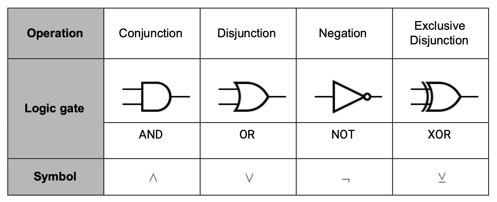
AND
- If both inputs are 1, then it outputs a 1
- Symbol of
^
--- |--\
    |   D ---
--- |--/
OR
- If either input is 1, then the output is 1
- Symbol of
v
--- |--\
     \   \
      }   } ------
     /   /
--- |--/
NOT
- Inverts the input
- Symbol of
¬
   |\
-- | >o ----
   |/
XOR
- Same as OR, but if both are 1, then return 0
- Notated as an underlined v
--- | |--\
    |  \   \
     }  }   } ------
    |  /   /
--- | |--/
(Or but with an extra curved line on the input side.)
NAND
Note
This isn’t on the spec
- Equal to !(A^B)
Order precedence
The order of operations matters, similarly to maths.
The sequence is:
- Brackets
- Not
- And
- Or
Laws of Boolean Algebra
Associative law
The associative law states that for 3 items and only one operator
de Morgan’s law
De Morgan’s law states that:
¬(A v B) = ¬A ^ ¬B

¬(A ^ B) = ¬A v ¬B
Note
You could think of this as distributing the ¬ symbol to the AND/OR, as well as the conditions.
This result can be proved with a truth table.
Distributive law:
The distributive law states that boolean algebra can be expanded out.
A ^ (B v C) = (A^B) v (A^C)
A v (B^C) = (A v B) ^ (A v C)
Absorptive law
A v (A^B^...) = A
A ^ (A v B v ...) = A
Karnaugh map
A karnaugh map is similar to a truth table, where it represents all of the possible outputs for possible inputs.
However, instead of a table, it is a grid, where the rows and columns are labelled with the possible inputs.
Karnaugh maps are much closer to normal tables, and are easier to read than truth tables.
| A/B | 0 | 1 |
|---|---|---|
| 0 | 0 | 0 |
| 1 | 0 | 1 |
In a Karnaugh map, there is a correct order for what the left side should look like. One bit should be different from the previous rows. For example:
| A/B | 00 | 01 | 11 | 10 |
|---|---|---|---|---|
| 00 | 0 | 0 | 0 | 0 |
| 01 | 0 | 0 | 0 | 0 |
| 11 | 0 | 0 | 0 | 0 |
| 10 | 0 | 0 | 0 | 0 |
| ^ Notice how the A/B column only differs by one bit each time. |
Given the example: P = !C^DvA^B
| . | A^B | 00 | 01 | 11 | 10 |
|---|---|---|---|---|---|
| !C^D | . | . | . | . | |
| 00 | . | 0 | 0 | 0 | 0 |
| 01 | . | 1 | 1 | 1 | 1 |
| 11 | . | 0 | 0 | 0 | 0 |
| 10 | . | 0 | 0 | 0 | 0 |
To reverse a KM:
- Group the adjacent 1s as big as they can be
- The groups must be minimised
- Groups must be of size $2^n$ where n is a whole number
- Ensure the groups are distinguishable
- Find the expression for each group
- Apply an OR to each group to combine them into the final condition
Logic Gates
Half Adder
A half adder is a circuit that adds 2 bits together, and outputs the sum and carry.
This is done by combining an XOR and AND gate together with inputs A and B.
It looks like this:

The half adder cannot take in an input carry bit. It will only produce an output carry.
Full Adder
A full adder is a circuit that is capable of taking in a carry bit, and adding it to the sum of 2 bits. By combining the output of one half adder with another half adder (and an additional OR for the carry in) it can correctly account for the carry in.

Legal, moral, cultural and ethical issues

Note
🚧 This page is currently being worked on. Please check back soon.
Computing related legislation

Note
🚧 This page is currently being worked on. Please check back soon.
Moral and ethical Issues

Note
🚧 This page is currently being worked on. Please check back soon.
Algorithms

Algorithms
Note
🚧 This page is currently being worked on. Please check back soon.
Search Algorithms

Note
🚧 This page is currently being worked on. Please check back soon.
Sorting Algorithms

Bubble sort
The bubble sort is a simple O(n^2) algorithm that sorts a dataset by iterating through the data with two pointers, switching the values where necessary.
Example
Consider the following array:[4, 2, 6, 8, 1, 3, 55, 9]
- This array is considered ‘unsorted’. To sort the array using Bubble sort, create two pointers pointing at index 0 and index 1.
 [4, 2, 6, 8, 1, 3, 55, 9]
  ⇑  ⇑
  p1 p2
- Since the value that p1 is pointing to is lower than the value at p2, the sorting algorithm will switch the two values around.
 [2, 4, 6, 8, 1, 3, 55, 9]
  ⇑  ⇑
  p1 p2
- The two pointers are then incremented.
 [2, 4, 6, 8, 1, 3, 55, 9]
     ⇑  ⇑
     p1 p2
- Since the two values dereferenced by the pointers are in the correct order, no switch is made. The pointers can be incremented.
 [2, 4, 6, 8, 1, 3, 55, 9]
        ⇑  ⇑
        p1 p2
- These two are also in the correct order, so no switch is made, then the pointers are incremented:
 [2, 4, 6, 8, 1, 3, 55, 9]
           ⇑  ⇑
           p1 p2
- These two are not in the correct order, so a switch is made.
 [2, 4, 6, 1, 8, 3, 55, 9]
           ⇑  ⇑
           p1 p2
- This loop continues until one pass is finished. (Skipped as an exercise for the reader.)
 [2, 4, 6, 1, 3, 8, 9, 55]
                    ⇑  ⇑
                    p1 p2
Important
Notice how the data isn’t sorted at this point. This is because bubble sort often requires more than one pass to sort the data.
This is what causes the algorithm to have an O(\(n^2\)) time complexity, since on average the algorithm will make one addition pass per additional element.
- After a few passes, eventually we will have a sorted dataset.
 [1, 2, 3, 4, 6, 8, 9, 55]
                    ⇑  ⇑
                    p1 p2
Once there is a pass where no elements are switched, then the algorithm returns.
Quicksort
Quicksort is a divide and conquer algorithm that has an average time complexity of O(\(nlogn\)). It works by choosing a ‘pivot’ element from the dataset, then moving it to the , and partitioning the other elements into two sub-arrays, according to whether they are less than or greater than the pivot.
The sub-arrays are then sorted recursively.
Note
This link may be helpful. I will not provide an example, since I don’t want this book to be impossibly big. The next section will rely on the visualiser with array size 10. Use those settings to follow along.
Pathfinding Algorithms

Note
🚧 This page is currently being worked on. Please check back soon.